· 7 min read
Chris Ottinger

Prefect.io is a python based Data Engineering toolbox for building and operating Data Pipelines. Out of the box, Prefect provides an initial workflow for managing data pipelines that results in a container image per data pipeline job.

The one-to-one relationship between data pipeline jobs and container images enables data engineers to craft pipelines that are loosely coupled and don't require a shared runtime environment configuration. However, as the number of data pipeline jobs grow the default container per job approach starts to introduce workflow bottlenecks and lifecycle management overheads. For example, in order to update software components used by flows, such as upgrading the version of Prefect, all the data pipeline job images have to be rebuilt and redeployed. Additionally the container image per job workflow introduces a wait time for data engineers to re-build data pipeline container images and test flows centrally on Prefect Server or Prefect Cloud environment.

Fortunately, Prefect comes to its own rescue with the ability to open up the box, exposing the flexibility in the underlying framework.

Out of the box - Prefect DockerStorage

Out of the box, Prefect provides a simple workflow for defining and deploying data pipelines as container images. After getting a first data pipeline running in a local environment, the attention turns to scaling up development and deploying flows into a managed environment, using either the Prefect Cloud service or a Prefect Server.

Combining Prefect Cloud or Prefect Server with Kubernetes provides a flexible and scalable platform solution for moving data pipelines into production. There are a number of options for packaging data pipeline flow code for execution on kubernetes clusters. The Docker Storage option provides the workflow for bundling the data pipeline job code into container images, enabling a common controlled execution environment and well understood distribution mechanism. The data pipeline runs as a pod using the flow container image.

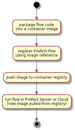
Prefect Docker Storage workflow steps for building and deploying data pipeline flows include:

Workflow Steps

  • packaging a flow (python code) as a serialised/pickled object into a container image
  • registering the flow using the container image name
  • pushing the container image to a container repository accessible from the kubernetes cluster
  • running the flow by running an instance of the named container image as a kubernetes pod

This is relatively simple immutable workflow. Each data pipeline flow version is effectively a unique and self contained 'point-in-time' container image. This initial workflow can also be extended to package multiple related flows into a single container image, reducing the number of resulting container images. But, as the number of data pipeline jobs grow, there issues of container image explosion and data engineering productivity remain.

Using Prefect GitStorage for flows addresses both container image proliferation as well as development bottlenecks.

Prefect Git Storage

Prefect Git Storage provides a workflow for developing and deploying data pipelines directly from git repositories, such as Gitlab or Github. The data pipeline code (python) is pulled from the git repository on each invocation with the ability to reference git branches and git tags. This approach enables:

  • reducing the number of container images to the number of different runtime configurations to be supported.
  • improving the data engineering development cycle time by removing the need to build and push container images on each code change.
  • when combined with kubernetes Prefect Run Configs and Job templates, enables selection of specific runtime environment images

Note that the GitStorage option does required access from the runtime kubernetes cluster to the central git storage service, e.g. gitlab, github, etc.

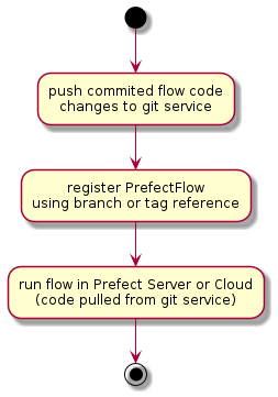
Prefect Git Storage workflow steps for 'building' and deploying data pipeline flows include:

Workflow Steps

  • pushing the committed code to the central git service
  • registering the flow using the git repository url and branch or tag reference
  • running the flow by pulling the reference code from the git service in a kubernetes pod

The container image build and push steps are removed from the developer feedback cycle time. Depending on network bandwidth and image build times, this can save remove 5 to 10 minutes from each deployment iteration.

Pushing the flow code

Once a set of changes to the data pipeline code has been committed, push to the central git service.

$ git commit
$ git push

Registering the flow

The flow can be registered with Prefect using either a branch (HEAD or latest) or tag reference. Assuming a workflow with feature branches:

  • feature branches: register the flow code using the feature branch. This enables the latest version (HEAD) of the pushed flow code to be used for execution. It also enables skipping re-registration of the flow on new changes as the HEAD of the branch is pulled on each flow run
  • main line branches: register pinned versions of the flow using git tags. This enables the use of a specific version of the flow code to be pulled on each flow run, regardless of future changes.

Determining the which reference to use:

# using gitpython module to work with repo info
from git import Repo

# presidence for identifing where to find the flow code
# BUILD_TAG => GIT_BRANCH => active_branch
build_tag = branch_name = None
build_tag = os.getenv("BUILD_TAG", "")
if build_tag == "":
branch_name = os.getenv("GIT_BRANCH", "")
if branch_name == "":
branch_name = str(Repo(os.getcwd()).active_branch)

Configuring Prefect Git storage:

from prefect.storage import Git
import my_flows.hello_flow as flow # assuming flow is defined in ./my_flows/flow.py

# example using Gitlab
# either branch_name or tag must be empty string "" or None
storage = Git(
repo_host=git_hostname,
repo=repo_path,
flow_path=f"{flow.__name__.replace('.','/')}.py",
flow_name=flow.flow.name,
branch_name=branch_name,
tag=build_tag,
git_token_secret_name=git_token_secret_name,
git_token_username=git_token_username
)

storage.add_flow(flow.flow)
flow.flow.storage = storage

flow.flow.regsiter(build=False)

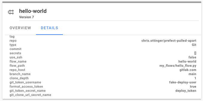
Once registered, the flow storage details can be viewed in the Prefect Server or Prefect Cloud UI. In this example, Prefect will use the HEAD version of the main branch on each flow run.

hello flow storage details

Next Steps - Run Config

With Prefect Git Storage the runtime configuration and environment management is decoupled from the data pipeline development workflow. Unlike with Docker Storage, with Git Storage, the runtime execution environment and data pipeline development workflows are defined and managed separately. As an added benefit, the developer feedback loop cycle time is also reduced.

With the data engineering workflow addressed, the next step in scaling out the Prefect solution turns to configuration and lifecycle management of the runtime environment for data pipelines. Prefect Run Configs and Job templates provide the tools retaining the flexibility on container image based runtime environments with improved manageability.
· 7 min read
Jeffrey Aven

When you want the SFTP service without the SFTP Server.

In implementing data platforms with external data providers, it is common to use a managed file transfer platform or an SFTP gateway as an entry point for providers to supply data to your system.

Often in past implementations this would involve deploying a sever (typically a Linux VM) and provisioning and configuring an SFTP service. If you wanted the data sent by clients to be copied to another storage medium (such as S3 or EFS) you would need to roll your own code or subscribe to a marketplace offering to do so.

I recently trialled the AWS Transfer Family SFTP gateway offering from AWS and sharing my adventures here.

Architecture

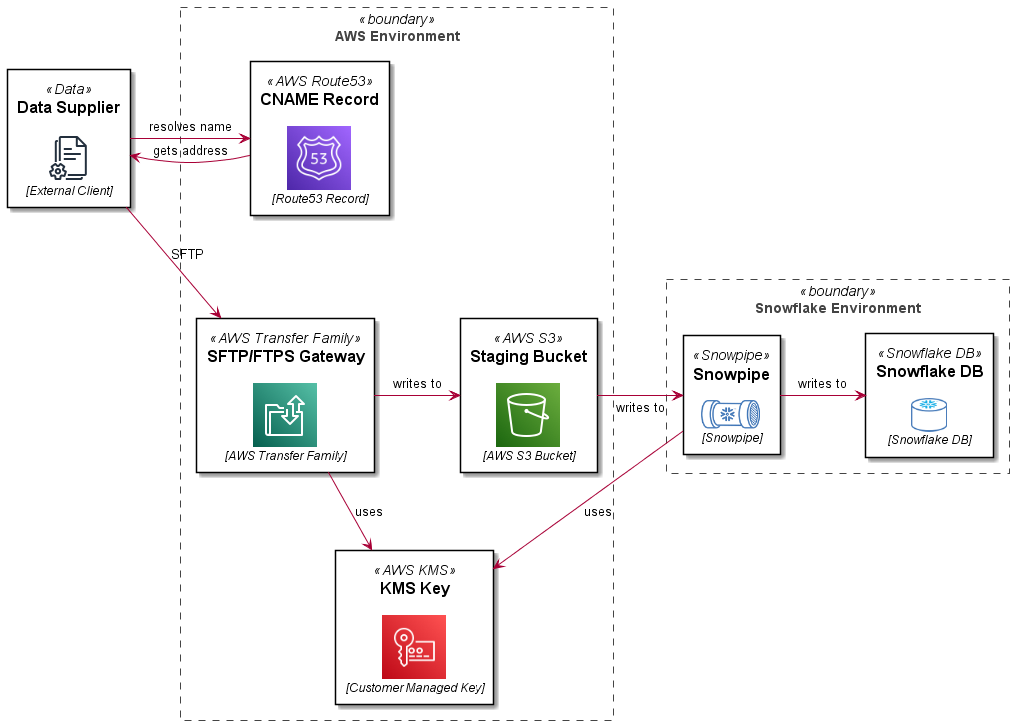
In this reference architecture, we are deploying an SFTP service which uses a path in an S3 bucket as a user’s home directory. Objects in the bucket are encrypted with a customer managed KMS key. The SFTP server front end address is mapped to a vanity URL using Route53. The bucket and path are integrated with a STORAGE INTEGRATION, STAGE and PIPE definition in Snowflake. The Snowflake bits are covered in more detail in this blog: Automating Snowflake Role Based Storage Integration for AWS. This article just details the AWS Transfer Family SFTP setup.

AWS Transfer SFTP Architecture

Setup

The steps to set up this pattern are detailed below.

info

This example uses the Jsonnet/CloudFormation pattern described in this article: Simplifying Large CloudFormation Templates using Jsonnet. This is a useful pattern for breaking up a monolithic CloudFormation template at design time to more manageable resource scoped documents, then pre-processing these in a CI routine (GitLab CI, GitHub Actions, etc) to create a complete template.

Setup the Service

To setup the SFTP transfer service use the AWS::Transfer::Server resource type as shown below:

note

Use the tags shown to display the custom hostname (used as a vanity url) in the Transfer UI in the AWS console.

Create the S3 Bucket

Create a bucket which will be used to store incoming files sent via SFTP.

note

This example logs to a logging bucket, not shown for brevity.

Create a Customer Managed KMS Key

Create a customer managed KMS key which will be used to encrypt data stored in the S3 bucket created in the previous step.

Create an IAM role to access the bucket

Create an IAM role which will be assumed by the AWS Transfer Service to read and write to the S3 staging bucket.

info

You must assign permissions to use the KMS key created previously, failure to do so will result in errors such as:

remote readdir(): Permission denied

User Directory Mappings

An SFTP users home directory is mapped to a path in your S3 bucket. It is recommended to use the LOGICAL HomeDirectoryType. This will prevent SFTP users from:

  • seeing or being able to access other users home directories
  • seeing the bucket name or paths in the bucket above their home directory

There are some trade offs for this which can make deployment a little more challenging but we will cover off the steps from here.

Create a Scoped Down Policy

A "scoped down" policy prevents users from seeing or accessing objects in other users home directories. This is a text file that will be sourced as a string into the Policy parameter of each SFTP user you create.

info

Using the LOGICAL HomeDirectoryType you don't have access to variables which represent the bucket, so this needs to be hard coded in the policy.txt document.

Also if you are using a customer managed KMS key to encrypt the data in the bucket (which you should be), you need to add permissions to the key - which again cannot be represented by a variable.

Failure to do so will result in errors when trying to ls, put, etc into the user's home directory such as:

Couldn't read directory: Permission denied
Couldn't close file: Permission denied

Since these properties are unlikely to change for the lifetime of your service this should not be an issue.

Create a user

Users are identified by a username and an SSH key, providing the public key to the server. A sample user is shown here:

tip

As discussed previously, it is recommended to use LOGICAL home directory mappings, which prevents users from seeing information about the bucket or other directories on the SFTP server (including other users directories).

Create a Route 53 CNAME record

Ideally you want to use a vanity url for users to access your SFTP service, such as sftp.yourcompany.com. This can be accomplished by using a Route 53 CNAME record as shown here:

Create some shared Tags

You would have noticed a shared Tags definition in many of the libsonnet files shown, an example Tags source file is shown here:

Pull it all together!

Now that we have all of the input files, lets pull them all together in a jsonnet file, which will be preprocessed in a CI process to create a template we can deploy with AWS CloudFormation.

Your customers would now connect to your service using they private key which corresponds to the public key they supplied to you in one of the previous steps, for example:

sftp -i mysftpkey jeffrey_aven@sftp.yourdomain.com

Add more users and enjoy!

if you have enjoyed this post, please consider buying me a coffee ☕ to help me keep writing!

· 4 min read
Jeffrey Aven

This article describes a simple SSO pattern for authenticating and authorizing users from an external AD and to your application without requiring federation.

the Challenge

You need to authenticate external users to use your application, these users belong to an organization using Azure Active Directory with specific login policies (such as password strength and expiry, multi factor authentication, etc). Your requirements (if you choose to accept them) are:

  1. You are required to provide SSO to these users using their home AD tenant and policies
  2. The solution does not include SAML based federation between directories (yours and theirs)
  3. The solution does not require any changes on the external AD tenant (no new AAD applications, client secrets, etc)

the Solution

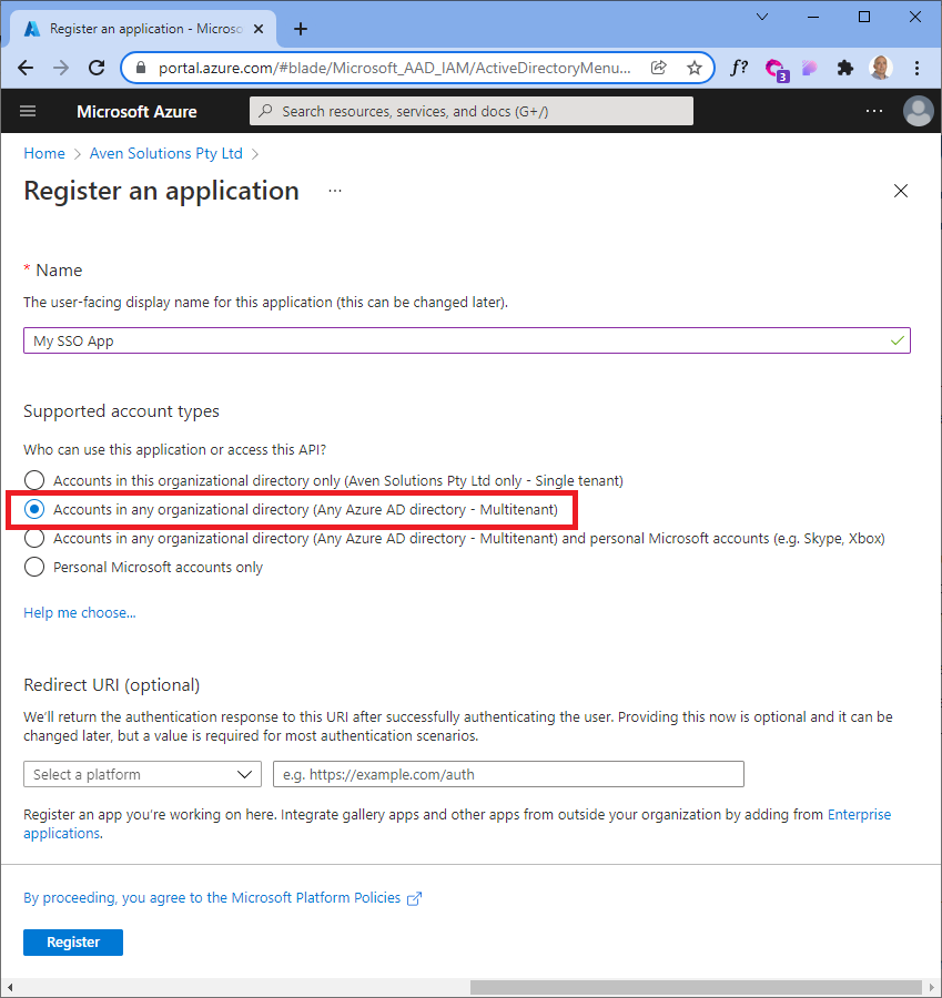
Using an IDAM/IDaaS platform (such as Okta in this case), along with an AAD application (in your AD tenant in your Azure subscription), you can create a local AD app using this magic property to accomplish all of the above requirements (requiring zero changes on the third-party AD).

Azure AD App Registration

This is what it looks like using the az cli:

the --available-to-other-tenants property is Microsoft's way of allowing you to implicitly trust other AAD/Office 365 tenants, meaning the authentication request is passed to the target AD tenant from your application.

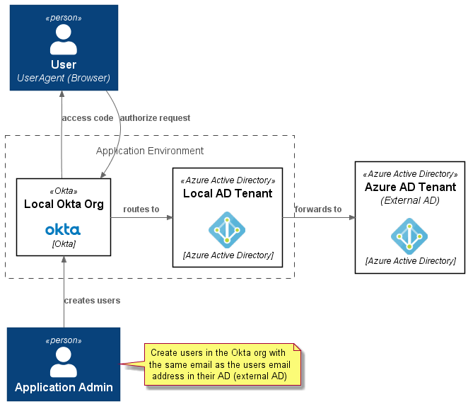
Here is a context diagram which explains the interactions in the context of a Jamstack application (using a library such as Auth.js).

Okta AD SSO Context Diagram

Setup and Configuration

The following flowchart explains the steps involved in setting this up. The highlighted nodes are part of normal application lifecycle operations as users get created and deactivated.

Okta AD SSO Setup Flowchart

Authorisation flow

The authorization flow for a public client (SPA) using PKCE (Proof Key for Code Exchange) is shown here:

Okta AD SSO Authorization Flow

Next up

Code! Stay tuned...

if you have enjoyed this post, please consider buying me a coffee ☕ to help me keep writing!

· 5 min read
Jeffrey Aven

Background

AWS Lambda instances will return UTC/GMT time for any date time object created using the Date.now() function in JavaScript as shown here:

let now = new Date();
const tzOffset = now.getTimezoneOffset();
console.log(`Default Timezone Offset: ${tzOffset}`);
// results in ...
// Default Timezone Offset: 0

Moreover, Lambda instances are stateless and have no concept of local time. This can make dealing with dates more challenging.

This is compounded for localities which have legislated Daylight Savings Time during part of the year.

Solution

A simple (vanilla JavaScript - no third party libraries or external API calls) to adjust the time to local time adjusted for Daylight Savings Time is provided here:

function getGmtDstTransitionDate(year, month, transitionDay, hour){
const firstDayOfTheMonth = new Date(year, month, 1);
let transitionDate = new Date(firstDayOfTheMonth);
// find the first transition day of the month if the first day of the month is not a transition day
if (firstDayOfTheMonth.getDay() !== transitionDay) {
transitionDate = new Date(firstDayOfTheMonth.setDate(firstDayOfTheMonth.getDate() + (transitionDay - firstDayOfTheMonth.getDay())));
};
// return the transition date and time
return new Date(transitionDate.getTime() + (hour * 60 * 60000));
};

function getLocalDateTime(date) {
// default to GMT+11 for AEDT
let offsetInHours = 11;
// if month is between April and October check further, if not return AEDT offset
// remeber getMonth is zero based!
if (date.getMonth() >= 3 && date.getMonth() <= 9) {
// DST starts at 0200 on the First Sunday in October, which is 1600 (16) on the First Saturday (6) in October (9) GMT
const dstStartDate = getGmtDstTransitionDate(date.getFullYear(), 9, 6, 16);
// DST ends at 0300 on the First Sunday in April, which is 1600 (16) on the First Saturday (6) in April (3) GMT
const dstEndDate = getGmtDstTransitionDate(date.getFullYear(), 3, 6, 16);
if (date >= dstEndDate && date < dstStartDate) {
offsetInHours = 10;
};
};
// return the date and time in local time
return new Date(date.getTime() + (offsetInHours * 60 * 60000));
}

// get current timestamp
let now = new Date();
console.log(`UTC Date: ${now}`);
now = getLocalDateTime(now);
console.log(`Local toLocaleString: ${now.toLocaleString()}`);

Breaking it down

This solution is comprised of two functions for DRY purposes.

The main function getLocalDateTime takes a date object representing the current time in UTC and returns a date object representing the local (DST adjusted) time.

The getLocalDateTime function sets a default DST adjusted offset in hours (11 in the case of AEDT), if the month is between April and October the getGmtDstTransitionDate is used to determine the exact boundaries between Standard Time and Daylight Savings Time.

In the case of AEST/AEDT this is the first Sunday in October at 0200 to enter Daylight Savings Time and the first Sunday in April at 0300 to end Daylight Savings Time (both dates and times are adjusted to their equivalent GMT times) and return to Standard Time (10 hours in the cases of AEST).

The offsetInHours variable and the arguments for getGmtDstTransitionDate can be easily modified for other timezones.

Tests

Some simple tests to run to check if the code is working correctly, to help with this I have set up the following unit test function:

function unitTest(inputDate, expOutputDate, testCase) {
if (getLocalDateTime(inputDate).toUTCString() === expOutputDate.toUTCString()) {
console.log(`TEST PASSED ${testCase}`)
} else {
console.log(`TEST FAILED ${testCase} : input date in GMT ${inputDate} should equal ${expOutputDate}`)
};
};

first create dates representing the beginning of Daylight Savings Time (immediately before the beginning, at the beginning and immediately after the beginning):

unitTest(new Date(2022, 9, 1, 15, 59, 59, 999), new Date(2022, 9, 2, 1, 59, 59, 999), "one ms before dst start");
// returns...
// ... INFO TEST PASSED one ms before dst start
unitTest(new Date(2022, 9, 1, 16, 0, 0, 0), new Date(2022, 9, 2, 3, 0, 0, 0), "dst start");
// returns...
// ... INFO TEST PASSED dst start
unitTest(new Date(2022, 9, 1, 16, 0, 0, 1), new Date(2022, 9, 2, 3, 0, 0, 1), "one ms after dst start");
// returns...
// ... INFO TEST PASSED one ms after dst start

next create dates similar tests representing the end of Daylight Savings Time (or beginning of Standard Time):

unitTest(new Date(2022, 3, 2, 15, 59, 59, 999), new Date(2022, 3, 3, 2, 59, 59, 999), "one ms before dst end");
// returns...
// ... INFO TEST PASSED one ms before dst end
unitTest(new Date(2022, 3, 2, 16, 0, 0, 0), new Date(2022, 3, 3, 2, 0, 0, 0), "dst end");
// returns...
// ... INFO TEST PASSED dst end
unitTest(new Date(2022, 3, 2, 16, 0, 0, 1), new Date(2022, 3, 3, 2, 0, 0, 1), "one ms after dst end");
// returns...
// ... INFO TEST PASSED one ms after dst end

Enjoy

if you have enjoyed this post, please consider buying me a coffee ☕ to help me keep writing!

· 5 min read
Jeffrey Aven

I have used the instructions here to configure Snowpipe for several projects.

Although it is accurate, it is entirely click-ops oriented. I like to automate (and script) everything, so I have created a fully automated implementation using PowerShell, the aws and snowsql CLIs.

The challenge is that you need to go back and forth between AWS and Snowflake, exchanging information from each platform with the other.

Overview

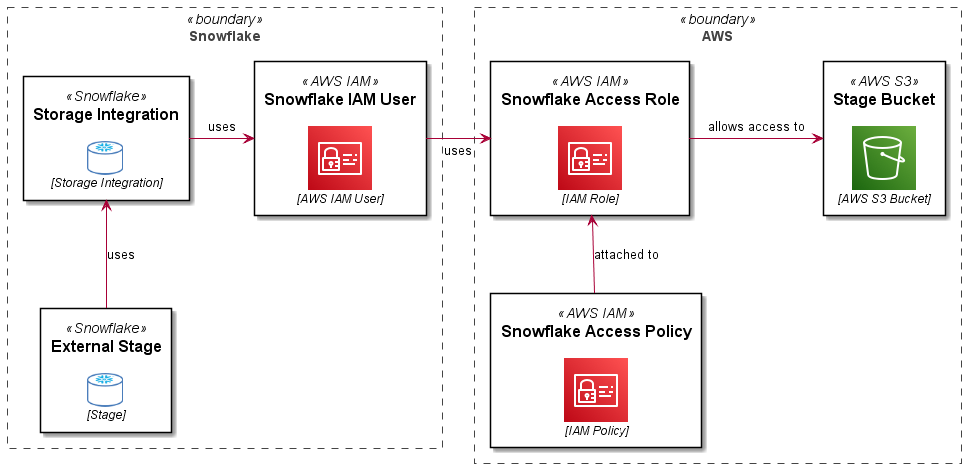
A Role Based Storage Integration in Snowflake allows a user (an AWS user arn) in your Snowflake account to use a role in your AWS account, which in turns enables access to S3 and KMS resources used by Snowflake for an external stage.

The following diagram explains this (along with the PlantUML code used to create the diagram..):

Snowflake S3 Storage Integration

Setup

Some prerequisites (removed for brevity):

  1. set the following variables in your script:
  • $accountid – your AWS account ID
  • $bucketname – the bucket you are letting Snowflake use as an External Stage
  • $bucketarn – used in policy statements (you could easily derive this from the bucket name)
  • $kmskeyarn – assuming you are used customer managed encryption keys, your Snowflake storage integration will need to use these to decrypt data in the stage
  • $prefix – if you want to set up granular access (on a key/path basis)
  1. Configure Snowflake access credentials using environment variables or using the ~/.snowsql/config file (you should definitely use the SNOWSQL_PWD env var for your password however)
  2. Configure access to AWS using aws configure
note

The actions performed in both AWS and Snowflake required privileged access on both platforms.

The Code

I have broken this into steps, the complete code is included at the end of the article.

Create Policy Documents

You will need to create the policy documents to allow the role you will create to access objects in the target S3 bucket, you will also need an initial “Assume Role” policy document which will be used to create the role and then updated with information you will get from Snowflake later.

Create Snowflake Access Policy

Use the snowflake_policy_doc.json policy document created in the previous step to create a managed policy, you will need the arn returned in a subsequent statement.

Create Snowflake IAM Role

Use the initial assume_role_policy_doc.json created to create a new Snowflake access role, you will need the arn for this resource when you configure the Storage Integration in Snowflake.

Attach S3 Access Policy to the Role

Now you will attach the snowflake-access-policy to the snowflake-access-role using the $policyarn captured from the policy creation statement.

Create Storage Integration in Snowflake

Use the snowsql CLI to create a Storage Integration in Snowflake supplying the $rolearn captured from the role creation statement.

Get STORAGE_AWS_IAM_USER_ARN and STORAGE_AWS_EXTERNAL_ID

You will need the STORAGE_AWS_IAM_USER_ARN and STORAGE_AWS_EXTERNAL_ID values for the storage integration you created in the previous statement, these will be used to updated the assume role policy in your snowflake-access-role.

Update Snowflake Access Policy

Using the STORAGE_AWS_IAM_USER_ARN and STORAGE_AWS_EXTERNAL_ID values retrieved in the previous statements, you will update the assume-role-policy for the snowflake-access-role.

Test the Storage Integration

To test the connectivity between your Snowflake account and your AWS external stage using the Storage Integartion just created, create a stage as shown here:

Now list objects in the stage (assuming there are any).

list @my_stage;

This should just work! You can use your storage integration to create different stages for different paths in your External Stage bucket and use both of these objects to create Snowpipes for automated ingestion. Enjoy!

Complete Code

The complete code for this example is shown here:

if you have enjoyed this post, please consider buying me a coffee ☕ to help me keep writing!